

How to interface sensors with electrical control systems?
Nov 18, 2026
Leave a message
If you’re deep in the electrical control equipment space, you know that sensors are the unsung heroes of any functional system—they’re the eyes, ears, and fingers that let control systems “see” environmental conditions, detect faults, and adjust operations in real time. But successfully interfacing sensors with electrical control systems isn’t just about hooking up a few wires. It’s a process that demands attention to signal compatibility, environmental resilience, and system design, especially when you’re working with the heavy-duty gear that powers industrial, commercial, and utility operations. As a supplier of Electrical Control Equipment, I’ve spent years walking clients through this process, troubleshooting missteps, and refining best practices to ensure seamless sensor integration. Let’s break down exactly how to get it right.
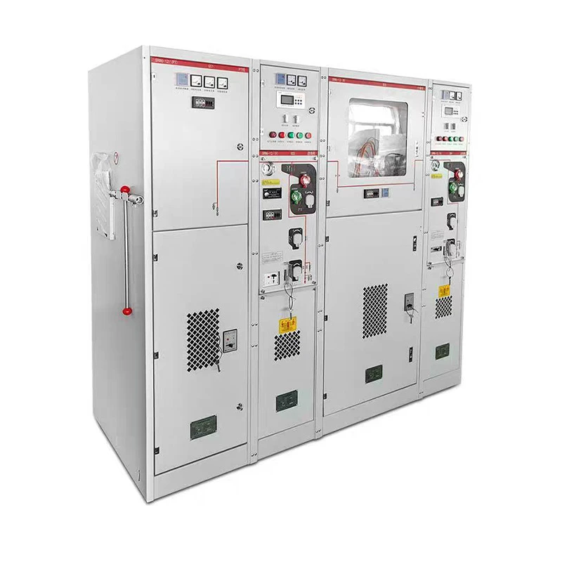
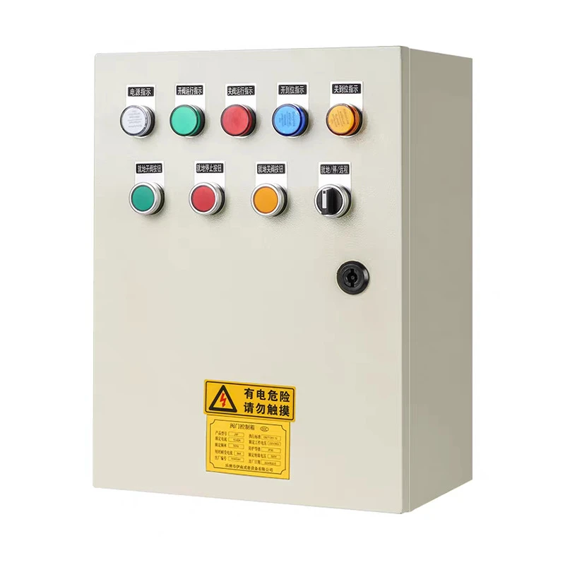
The first and most critical step in any sensor-control system interface is understanding the core needs of your application. A sensor that works perfectly for a small-scale HVAC system will fail in a high-voltage industrial motor control setup, for example. Let’s define the basics: sensors convert physical or chemical phenomena—temperature, pressure, voltage, current, gas leaks—to electrical signals that a control system (like a PLC, DCS, or relay-based control panel) can interpret. The type of sensor you choose dictates a lot about how you’ll interface it, and that choice starts with defining your system’s requirements.
For context, many of our clients at Electrical Control Equipment operate on medium-voltage (MV) networks, which means their sensors need to handle high noise levels, extreme ambient temperatures, and potential electrical surges. Let’s take a common use case: a client managing a power distribution substation. They need current sensors to monitor load on their distribution switchgear, temperature sensors to detect overheating in their medium voltage cabinets, and gas sensors to alert for leaks in enclosed switchgear or gas-insulated switchgear cabinets. Each of these sensors has unique signal outputs, and mismatching that to your control system is the fastest way to get inaccurate data or a system that won’t work at all.
Next, signal compatibility is non-negotiable. Sensors output signals in a few standard formats, and your control system needs to match—or translate—these to function properly. The most common signal types are analog (4-20mA is the industrial standard for most environments, as it’s resistant to noise) and digital (like Modbus RTU, PROFINET, or IO-Link). Let’s say you’re using a temperature sensor that outputs a 0-10V analog signal; your control system needs an analog input (AI) module to read that. If your sensor uses a digital fieldbus protocol, you’ll need to make sure your control system has compatible fieldbus cards or gateways to translate the data.
One mistake I see all the time is mixing signal types because of cost. For example, a client might try to use a cheap 0-5V sensor for a noisy industrial plant, only to have signal corruption from nearby power lines. 4-20mA is better here because it uses current variation (not voltage) for signaling, so electrical interference from adjacent wiring barely affects the reading. Digital sensors are often more reliable for long distances, as they can transmit data over hundreds of meters without signal loss, which is a big plus for large switchgear rooms or outdoor MV cabinets. When working with enclosed switchgear, where space is tight and wiring is often routed in confined areas, choosing the right signal type reduces installation complexity and long-term maintenance headaches.
Wiring and installation practices are the next piece of the puzzle, and they can make or break even the best sensor-control pairing. Poor wiring is responsible for 70% of sensor signal errors in industrial systems, according to a 2022 study by the International Society of Automation (ISA). Let’s cover the key rules here. First, separate signal wiring from power wiring. If you run 480V power lines right next to low-voltage sensor wires, you’ll get electromagnetic interference (EMI) that skews readings. Use shielded twisted-pair cable for analog sensors, and ground the shield at only one end (not both) to avoid ground loops, which are a common source of noise.
For high-voltage applications like gas-insulated switchgear cabinets or medium voltage cabinets, you’ll also need to follow arc flash and safety standards. Sensors installed near high-voltage busbars must have insulation ratings that match the system’s voltage level, and their mounting should be designed to prevent physical damage or accidental contact. When routing wires inside enclosed switchgear, use cable glands designed for the cabinet’s enclosure rating (IP or NEMA) to keep out dust, moisture, and corrosive fumes—especially critical in outdoor or harsh industrial environments where switchgear is exposed to extreme weather.
Then there’s the matter of powering your sensors. Most sensors draw a small amount of power (often 12-24V DC), but you can’t just tap power from any location in your control system. If you power multiple low-voltage sensors from a single supply that’s also used for high-current actuators, voltage drops or power spikes will cause sensors to malfunction. Instead, use dedicated power supplies for sensors, rated for the total current draw of all connected sensors, and include surge protection. For systems with long cable runs, remember that voltage drop becomes a factor: a 24V DC supply might only deliver 21V at a sensor 100 meters away, which is enough to make the sensor output incorrect or stop working entirely.
Once the sensors are wired up to the control system, the next step is configuration and calibration. This is where you turn raw signals into actionable data. Most control systems require you to set input ranges: for a 4-20mA current sensor, you’ll tell the control system that 4mA = 0A load and 20mA = 100A load, for example. Calibration is equally important, as even a perfectly installed sensor can drift over time, especially in high-vibration environments common in manufacturing plants or utility substations.
I always recommend that clients test each sensor individually before connecting it to the full control system. For a temperature sensor, you can simulate a known temperature and verify that the control system reads the correct value. For a current sensor, use a precision current source to check the signal output against the expected value. This step catches bad sensors or wiring errors early, saving you the hassle of troubleshooting a full system shutdown later. When working with distribution switchgear, where an incorrect current reading can lead to unplanned outages, this testing step is non-negotiable.
Integration with the control system’s logic is the final piece that turns sensor data into action. A control system isn’t just a data logger—it uses sensor data to make decisions. For example, if a temperature sensor on a medium voltage cabinet reads 120°C (well above the 80°C safe operating limit), the control system should trigger an alarm, shut down the associated circuit, or activate a cooling fan. If a gas sensor in enclosed switchgear detects a leak, the system should alert operators and isolate the affected area. This logic is programmed into the control system’s software, and it’s critical that the sensor data is reliable enough to make these decisions. If your sensor is giving incorrect temperature readings, the control system might shut down a functional circuit unnecessarily, or miss a real fault.
There are also advanced considerations for more complex systems, like those using predictive maintenance. Today’s modern electrical control systems often integrate cloud-based platforms that use sensor data to predict when equipment will fail, rather than just reacting to faults. To enable this, sensors need to support protocols like MQTT or OPC UA, which let them transmit data to cloud servers. For clients with large fleets of switchgear (including gas-insulated switchgear cabinets and distribution switchgear), this type of integration can cut maintenance costs by 20-30% by addressing issues before they cause downtime.
Through all of this, it’s important to partner with a supplier that understands both sensor technology and electrical control systems. At our company, we don’t just sell Electrical Control Equipment—we help clients select the right sensors for their applications, design integration strategies that avoid common pitfalls, and provide ongoing support for testing and calibration. Whether you’re building a new enclosure switchgear setup or upgrading an existing distribution control system, we can walk you through every step of the process to ensure your sensors and control system work in perfect harmony.
If you’re planning a project that involves sensor integration with electrical control systems, or if you have questions about which switchgear or control equipment is right for your needs, we’d love to connect. Our team has years of experience working with industrial, commercial, and utility clients, and we can help you design a system that is reliable, compliant, and tailored to your specific operational requirements.
References
International Society of Automation. (2022). Sensor Signal Integrity in Industrial Control Systems. ISA Press.
Miller, J. (2021). “Best Practices for Wiring Sensors to PLCs.” Control Engineering Magazine, Vol. 68, No. 4, pp. 22-27.
National Electrical Manufacturers Association. (2020). Application Guide for Medium Voltage Switchgear and Associated Sensors. NEMA Standards Publication SG-2020.
Send Inquiry