

How to test the efficiency of a high frequency power inductor?
Nov 17, 2026
Leave a message
If you’re working in power electronics—whether you’re a design engineer, procurement lead, or just someone trying to get their high-frequency power inductor right—you know the struggle: a part that works on paper, but dies or underperforms in the actual circuit. That’s why testing efficiency isn’t just a checkbox; it’s the make-or-break step to making sure your inductors don’t waste power, overheat, or crash your whole system. As a supplier who’s been deep in the high-frequency power inductor game for years, I’ve seen so many teams skip key tests and end up with avoidable headaches. Today, I’m walking through the practical, no-fluff ways we test efficiency, plus where our line of parts—from the high frequency power inductor to specialized components like AC choke coils—fit into this process. Let’s dive in.
First, let’s get one thing straight: efficiency here isn’t just “95% good, 98% better.” High frequency power inductors (HFPI) are used in everything from EV inverters to fast chargers, so even a 1% efficiency gap can mean thousands in wasted energy or overheating parts. The main culprits that drag efficiency down are copper loss (from the coil’s resistance) and core loss (from the magnetic material itself, especially at high frequencies like 100kHz+), plus parasitic stuff like stray capacitance or eddy currents. To test these, you need a setup that mimics real-world conditions—not just a bench test with a signal generator. Let’s break down the core steps we use at our shop, and how each ties to validating a part from our line of High Power Inductor or Power Inductor Coil offerings.
Step 1: Build a Realistic Test Bench (No Half-Measures)
I’ve seen teams use generic signal generators and cheap resistors for efficiency tests, and the results are totally useless. High frequency circuits have weird behaviors that low-frequency test gear can’t pick up. Your test bench needs to mirror the exact circuit the inductor will live in: that means matching the switching frequency (say, 500kHz for a GaN charger), the load range (from light load to full load, since inductors behave differently there), and the voltage levels (battery voltages for EVs vs. 12V for a laptop charger).
What you actually need for the bench: a programmable power supply (to mimic the input voltage), a digital power analyzer (this is non-negotiable—It measures input and output power with tiny errors, down to 0.1% or better), a load bank to dial in from 10% to 100% load, and a oscilloscope to peek at waveforms (more on that later). For testing parts like our high frequency power inductor or custom inductive components, we also use a temperature chamber if the end application sees extreme temps, since core loss changes when it’s hot or cold.
Pro tip: If you’re testing multiple parts (like comparing a ferrite core vs. powdered iron core coil), keep every other variable identical—same bench setup, same PCB layout, same wiring. That way, any efficiency difference is actually from the inductor, not something you messed up in the test. And for our customers testing our AC choke coil line, this same bench works, just adjust the frequency and load to match their AC application.
Step 2: Measure Power Losses (Copper vs. Core—Separate Them!)
Total inefficiency is just total power loss, right? But if you can tell how much is copper loss vs. core loss, you can fix the right problem. Copper loss is I²R—simple: it’s the resistance of the coil times the square of the current going through it. Easy to measure with a multimeter, but wait—at high frequencies, the current doesn’t distribute evenly across the coil wire, thanks to skin effect and proximity effect. That makes the AC resistance higher than DC resistance, which kills efficiency. So instead of just testing DC resistance, we use an LCR meter at the exact operating frequency (say, 250kHz) to get the AC resistance of our Power Inductor Coil parts. That’s the real number you need for copper loss.
Core loss is trickier. Core loss comes from the magnetic material oscillating and generating heat, and it skyrockets at high frequencies. To measure this, we use the “extrapolation method” with the power analyzer: first, measure total power loss at a given load and frequency, then subtract the copper loss we calculated from the AC resistance and actual current. The remaining number is core loss. For our high frequency power inductor line, we test core loss at up to 1MHz, because that’s where a lot of next-gen chargers and DC-DC converters operate. If core loss is too high, we can swap core materials (like sending from a standard ferrite to a nanocrystalline core) without retooling the whole coil—something we do for customers who need maximum efficiency at high frequencies.
Step 3: Check Waveform Distortion (It’s a Hidden Efficiency Killer)
You might have perfect power numbers on the analyzer, but if the waveforms are messy, that means the inductor isn’t doing its job storing and releasing energy properly, which adds hidden loss. Use an oscilloscope to probe the voltage across the inductor and the current through it. At high frequencies, if the current waveform is jagged or distorted (instead of a smooth triangle wave for a DC-DC converter), that’s from parasitic capacitance in the coil or core, or the inductor saturating under load. Saturation is a big one—if the inductor’s core saturates at full load, it can’t store enough energy, so you get extra switching losses that drag efficiency down.
For example, if you test a part from our High Power Inductor line and see current spikes at turn-on, that might mean we used a core that’s too small for the current rating. We catch this during our waveform tests, and adjust the core size before shipping to customers. Another thing: phase shift between voltage and current. The power factor (which ties into efficiency) gets worse if there’s a big phase shift, so we target a phase angle of less than 5 degrees at rated frequency and load for all our inductive components.
Step 4: Temperature Testing (Efficiency Changes When It’s Hot)
Inductors warm up when they run, and that heat changes their resistance and core loss, which changes efficiency. You can’t test at room temp and call it a day—you need to run the inductor at full load for an hour, then measure efficiency at operating temperature, and also do thermal cycling tests (freeze it, heat it) to make sure efficiency doesn’t drop over time. We put every high frequency power inductor we sell into a thermal chamber, run it at rated load for 2 hours, then measure the temperature rise (usually we aim for less than 30C rise at full load) and recalculate efficiency. If a part runs too hot, that means we need to adjust the wire gauge or core shape to reduce copper or core loss.
I remember a customer a few years back who was testing our AC choke coil for a solar inverter. They tested at room temp and got 98.5% efficiency, but at full operating temp (60C), it dropped to 97.8%. Turns out their inverter’s switching frequency was higher than they’d specified, so core loss went up when it got hot. We swapped them to a higher-grade ferrite core, and their efficiency went back up to 98.4% at operating temp. That’s exactly why temperature testing is non-negotiable.
Step 5: Real-World Load Testing (Light Load vs. Full Load)
A lot of inductors are great at full load but terrible at light load (like when a phone charger is plugged in but not charging). Efficiency at light load is huge for battery-powered devices, since they’re often in idle mode. To test this, we dial the load down from 100% to 1% (or as low as your application uses) and measure efficiency at each step. For our High Power Inductor parts used in EVs, light load efficiency matters too, because EVs have multiple systems that run at partial load most of the time.
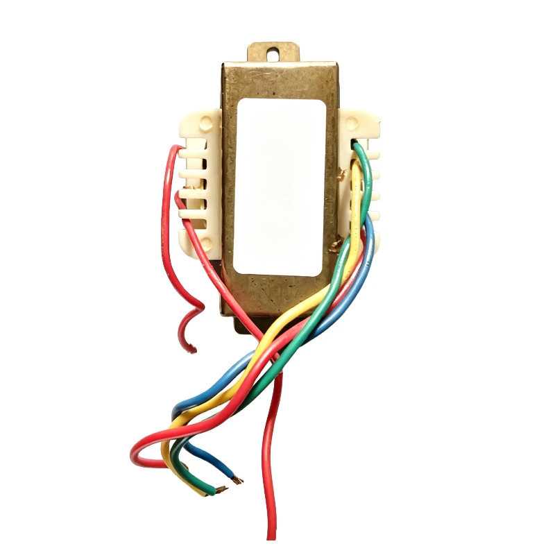
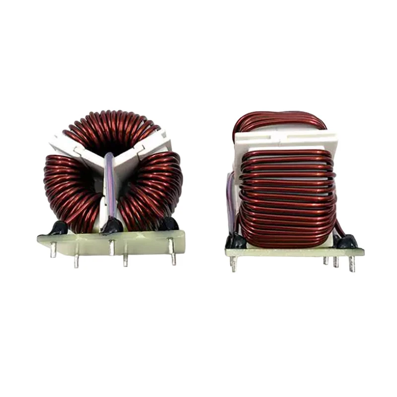
The big mistake here is only testing at full load. We once had a customer who complained our power inductor coil was wasting battery power in their e-bike. Turns out they only tested at full throttle, but the inductor was super inefficient when the bike was cruising at half speed. We adjusted the core gap to reduce magnetizing current, which fixed light load efficiency, and they saved almost 5% battery power in cruise mode. That’s the kind of issue you only catch by testing across the entire load range.
Common Mistakes We See Customers Make (And How to Fix Them)
Let’s get real—most of the efficiency issues we help customers with come from skipping these tests, or doing them wrong. Here are the top ones:
- Forgetting AC resistance: Using DC resistance from a multimeter instead of AC resistance at operating frequency. That makes copper loss look way lower than it actually is.
- Ignoring saturation: If the inductor saturates under load, efficiency plummets fast. Always check the current at which saturation happens with an oscilloscope, not just the rated current on the datasheet.
- Poor test setup: Long wires or messy PCB traces add their own resistance and inductance, skewing efficiency numbers. Keep the test bench as close to the actual circuit as possible.
- Only testing at one frequency: High frequency power inductors’ efficiency changes with frequency, so test at all frequencies your application uses.
If you’re shopping around for a reliable supplier, check if they do these tests—we do every single one in our in-house lab, and we can share test reports for any of our parts, from high frequency power inductor to custom inductive components. We’re not just selling parts; we test them to make sure they work in your circuit, not just on a spec sheet.
Wrapping Up: Efficiency = Test, Test, Test (And Don’t Cut Corners)
At the end of the day, testing the efficiency of a high frequency power inductor isn’t rocket science, but it does require doing it right. You need a realistic test bench, measure copper and core loss separately, check waveforms and saturation, test at temperature, and run through the full load range. For us, this process isn’t just a quality step—it’s how we build parts that our customers can trust. Whether you need a High Power Inductor for a solar inverter, an AC choke coil for a motor drive, or a custom Power Inductor Coil for a next-gen charger, we’ve got the test data to back it up.
If you’re working on a project and need help testing your current inductors, or want to see how our high frequency power inductor line can solve your efficiency issues, reach out to our team to talk through your requirements. We’re here to help you get the right part the first time, no wasted time or money.
References
- Electrical Engineering Textbook: Principles of Power Electronics (5th Edition), Erickson and Maksimovic
- Inductor Efficiency Testing Guidelines, International Electrotechnical Commission (IEC) Standard 62368-1
- High Frequency Inductor Core Loss Characterization, Journal of Applied Magnetics and Magnetic Materials, 2022
- Power Inductor AC Resistance Calculation, Texas Instruments Application Note SLVA795
Send Inquiry